Computer Aided Design (CAD) software was created in the late 1960’s to accelerate the engineering drawing process. While CAD was historically used in engineering, drawing and construction architecture, it is now widely used for creating metal fabrication designs, and has superseded the time-consuming process of manually creating technical drawings.
CAD enables sheet metal fabricators to design prototypes, products, machines, or structures by providing a digital drafting space. It greatly increases productivity, design, drawing quality, documentation, information communication, and database maintenance. The output of a CAD program comes in the form of soft-copy electronic files that can be used for printing or for digital machining.
The diagrams and models produced using CAD can either be two dimensional (2D) or three dimensional (3D). CAD programs allows sheet metal fabricators to rotate and orbit around their designs, meaning they can check the lines produced from all possible angles, and thereby eliminate the potential for error.
What are the different types of CAD software?
2D CAD Drafting Software
2D CAD is the forerunner of CAD software and was created in the early 70s. At that time, major automobile, aerospace, and other engineering companies developed in-house tools to automate repetitive drafting requirements. 2D CAD relies on basic geometric shapes like lines, rectangles, circles, among others, to produce flat drawings.
While it is rarely used in the sheet metal industry today, other industries continue to use 2D CAD software packages such as AutoCAD. A popular example is the creation of 2D floor plans for the real estate and drafting industries.
Examples of when 2D CAD may be preferred over 3D CAD:
- When the models do not need any 3D functionality
- Designs are required for a single component
- When drawings require less space
- Tight deadlines to complete a project as well as a smaller budget
Here is a video which showcases the 2D CAD Drafting process in AutoCAD.
3D CAD Drafting Software
3D CAD is a step up from the original 2D CAD software and was introduced in the 1980’s by a partnership between IBM and Dassault Systems. As the processing power of computers increased and the graphic display capabilities improved, 3D CAD became a progressively more popular design tool, particularly for sheet metal manufacturers and fabricators. 3D CAD allows the creation of 3D images that are realistic and that can be viewed and rotated in any direction. You can also display views from a 3D model, such as isometrics or perspectives, from any angle using 3D CAD.
While 2D drafting is more cost efficient, 3D CAD drafting has three main advantages. Firstly, a 2D drawing does not work easily with downstream systems like purchasing and manufacturing, meaning that ordering the right size and quantity of materials to build the design can be more cumbersome and prone to error. Secondly, although errors can arise in both 2D and 3D CAD, the rotation of designs and models in 3D CAD allows errors to be identified earlier and fixed prior to fabrication and manufacturing. Finally, and most importantly, because models are built in 3D, and can be viewed from any perspective, this allows for more accurate and efficient manufacturing, resulting in a better-quality product overall. For these reasons, 3D CAD is becoming the industry standard for sheet metal fabricators.
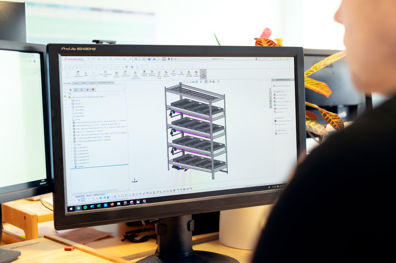
One of the most widely used 3D CAD software packages is SolidWorks CAD. The video below showcases some of its capabilities.
State of the art CAD software at E&A Probend
At E&A Probend we use SolidWorks CAD to create product prototypes prior to manufacturing. SolidWorks CAD is one of the most proficient and advanced CAD software systems available that is built specifically for design and engineering and even more specifically, for sheet metal manufacturing. Building 3D designs helps us to conceptualize, create, confirm, communicate, manage, and transform our clients’ ideas and projects into excellent product design. With this software, we can build components, assemblies, enclosures, and much more with purpose-built, parametric sheet metal design tools. We make projects come to life with custom models tailored to each client’s exact and unique specifications and requirements.
Our team of design experts can work with your ideas, drawings, or sketches to help you build a 3D model of your product in SolidWorks CAD. We can then make recommendations to optimise and improve your product. By designing your product in SolidWorks CAD first, your designs can be used to lodge patents more easily and efficiently. This protects your intellectual property and increases commercial opportunities.
To find out more, or discuss your next metal project, please get in touch with us any time.